Overview
In this lesson, you will learn how to change the brightness of an LED by using different values of resistor.
Parts Required5mm led
5mm LED - 1nos

270 Ω Resistor (red, purple, brown stripes) -1 nos

470 Ω Resistor (yellow, purple, brown stripes) - 1 nos


2.2 kΩ Resistor (red, red, red stripes) - 1 nos


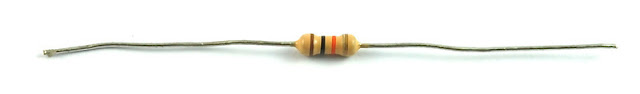
10 kΩ Resistor (brown, black, orange stripes) - 1 nos

Breadboard - 1 nos


Arduino Uno R3 - 1 nos


Jumper wire pack - 1 nos


LED's
LED's make great indicator lights. They use very little electricity and they pretty much last forever.They are durable and power saving.
In this lession you will use perhaps the most common of all LEDs a 5mm red LED. 5Mm refers to the diameter of the LED and as well as 5mm, other common sizes are 3mm and 10mm LEDs. Although 10mm leds are not commonly found
You cannot directly connect an LED to a battery or voltage source. Firstly, because the LED has a positive and a negative lead and will not light if they are the wrong way around and secondly, an LED must be used with a resistor to limit the amount of current flowing through the LED - otherwise there are chances of led burn out.

If you do not use a resistor with an LED, then it may well be destroyed almost immediately, as too much current will flow through the LED, heating of LED takes place and destroying the 'junction' where the light is produced due to avalanche breakdown.
There are two ways to identify the positive terminal and negative terminal of a LED
Firstly, the positive lead is longer.
Secondly, where the negative lead enters the body of the LED, there is a flat edge to the case of the LED.
If you happen to have an LED that has a flat side next to the longer lead, you should assume that the longer lead is positive.
Resistors
As the name suggests, resistors resist the flow of current and the higher the value of the resistor, the more it resists and the less electrical current will flow through it. We are going to use this to control how much Current flows through the LED and therefore how brightly it shines.lower the resistance, higher will be the brightness of led and higher the resistance, lower will be the brightness of led.
But first, a bit more about resistors.
The unit of resistance is called the Ohm, which is usually shortened to Ω the Greek letter Omega. Because an Ohm is a low value of resistance (it doesn't resist much at all), we also give the values of resistors in kΩ (1000 Ω) and MΩ (1000,000 Ω). These are called kilo-ohms and mega-ohms.
In this lesson, we are going to use four different values of resistor, 270Ω, 470Ω, 2.2kΩ and 10kΩ. These resistors all look the same, except that they have different colored stripes on them. These stripes tell you the value of the resistor.
The resistor color code works like this, for resistors like this with three colored stripes and then a gold stripe at one end.
Each color has a number, as follows:
Black 0
Brown 1
Red 2
Orange 3
Yellow 4
Green 5
Blue 6
Purple 7
Gray 8
White 9
The first two striped are the first two digits of the value, so red, purple means 2, 7. The next stripe is the number of zeros that need to come after the first two digits, so if the third stripe is brown, as it is in the photograph above, then there will be one zero and so the resistor is 270Ω.
A resistor with stripes brown, black, orange is 10 and three zeros so 10,000 Ω in other words 10 kΩ.
The next strip is which is gold indicated the tolerance band which indicates the value of resistor is not exactly 10kΩ it can be 9.9 or 10.5 ie is +- 5% tolerance over the value if resistor
Unlike LEDs, resistors do not have a positive and negative lead. They can be connected either way around.Resistors are bipolar in nature

The Arduino is a convenient source of 5 Volts, that we will use to provide power to the LED and resistor. You do not need to do anything with your Arduino, except plug it into a USB cable.

With the 270 Ω resistor in place, the LED should be quite bright. If you swap out the 270 Ω resistor for the 470 Ω resistor, then the LED will appear a little dimmer. With the 2.2kΩ resistor in place the LED should be quite faint. Finally, with the 10 kΩ resistor in place, the LED will be just about visible. Pull the red jumper lead out of the breadboard and touch it into the hole and remove it, so that it acts like a switch. You should just be able to notice the difference.
Turning out the lights might help even more.

Note, you will probably want to put the 270Ω resistor back in place.
So, it does not matter which side of the LED we put the resistor, as long as it is there somewhere.
The unit of resistance is called the Ohm, which is usually shortened to Ω the Greek letter Omega. Because an Ohm is a low value of resistance (it doesn't resist much at all), we also give the values of resistors in kΩ (1000 Ω) and MΩ (1000,000 Ω). These are called kilo-ohms and mega-ohms.
In this lesson, we are going to use four different values of resistor, 270Ω, 470Ω, 2.2kΩ and 10kΩ. These resistors all look the same, except that they have different colored stripes on them. These stripes tell you the value of the resistor.
The resistor color code works like this, for resistors like this with three colored stripes and then a gold stripe at one end.
Each color has a number, as follows:
Black 0
Brown 1
Red 2
Orange 3
Yellow 4
Green 5
Blue 6
Purple 7
Gray 8
White 9
The first two striped are the first two digits of the value, so red, purple means 2, 7. The next stripe is the number of zeros that need to come after the first two digits, so if the third stripe is brown, as it is in the photograph above, then there will be one zero and so the resistor is 270Ω.
A resistor with stripes brown, black, orange is 10 and three zeros so 10,000 Ω in other words 10 kΩ.
The next strip is which is gold indicated the tolerance band which indicates the value of resistor is not exactly 10kΩ it can be 9.9 or 10.5 ie is +- 5% tolerance over the value if resistor
Unlike LEDs, resistors do not have a positive and negative lead. They can be connected either way around.Resistors are bipolar in nature
Breadboard Layout

The Arduino is a convenient source of 5 Volts, that we will use to provide power to the LED and resistor. You do not need to do anything with your Arduino, except plug it into a USB cable.

With the 270 Ω resistor in place, the LED should be quite bright. If you swap out the 270 Ω resistor for the 470 Ω resistor, then the LED will appear a little dimmer. With the 2.2kΩ resistor in place the LED should be quite faint. Finally, with the 10 kΩ resistor in place, the LED will be just about visible. Pull the red jumper lead out of the breadboard and touch it into the hole and remove it, so that it acts like a switch. You should just be able to notice the difference.
Turning out the lights might help even more.
Moving the Resistor
At the moment, you have 5V going to one leg of the resistor, the other leg of the resistor going to the positive side of the LED and the other side of the LED going to GND. However, if we moved the resistor so that it came after the LED, as shown below, the LED will still light.

So, it does not matter which side of the LED we put the resistor, as long as it is there somewhere.
No comments:
Post a Comment